Checkweigher and Packaging Line Machine Safety: Guards, Interlocks or Light Curtains?
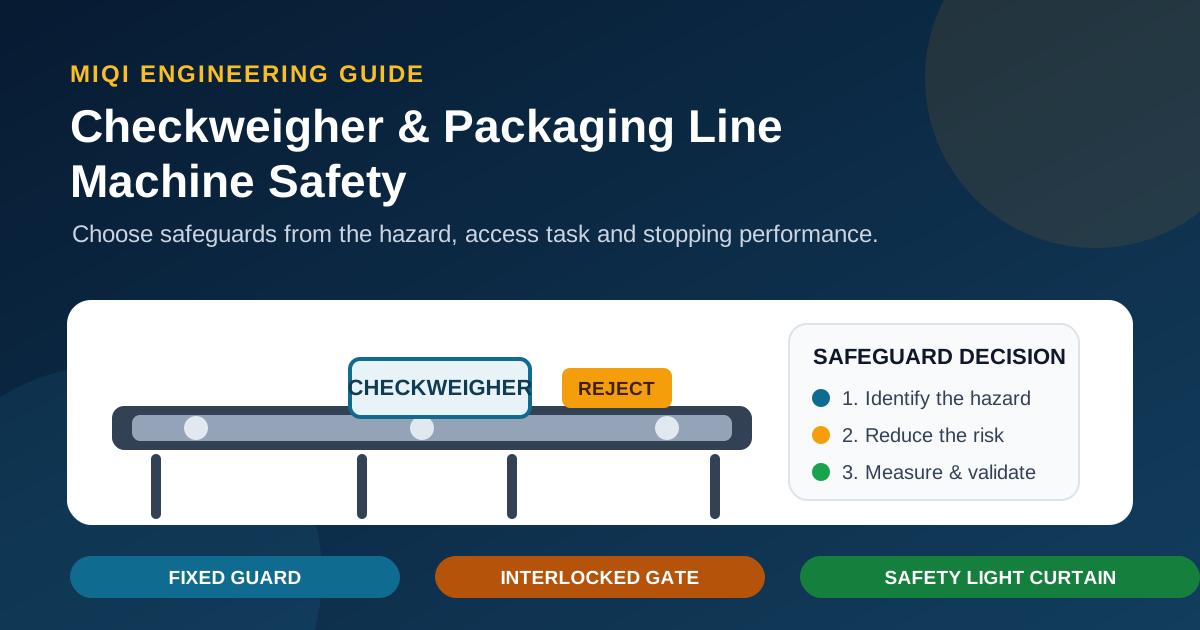
Not every checkweigher needs a safety light curtain. Start with the real hazard and the tasks that bring people close to it. Use fixed guards where routine access is unnecessary; use interlocked access, with guard locking where danger remains after a stop request, for repeated entry; and use a safety light curtain only where the opening must remain accessible and the machine can reach a validated safe state before a person reaches the hazard.
1. Map the real hazard zones before selecting a device
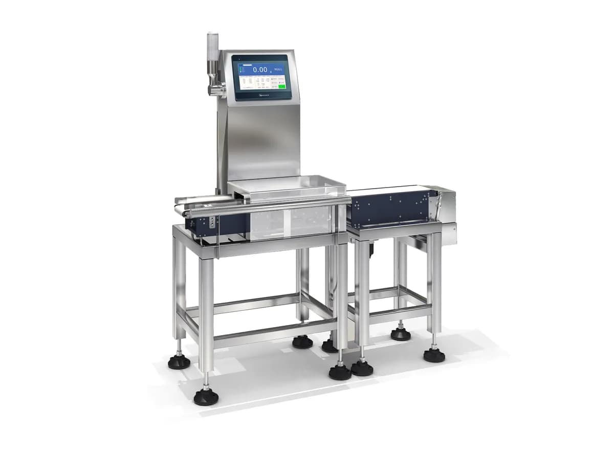
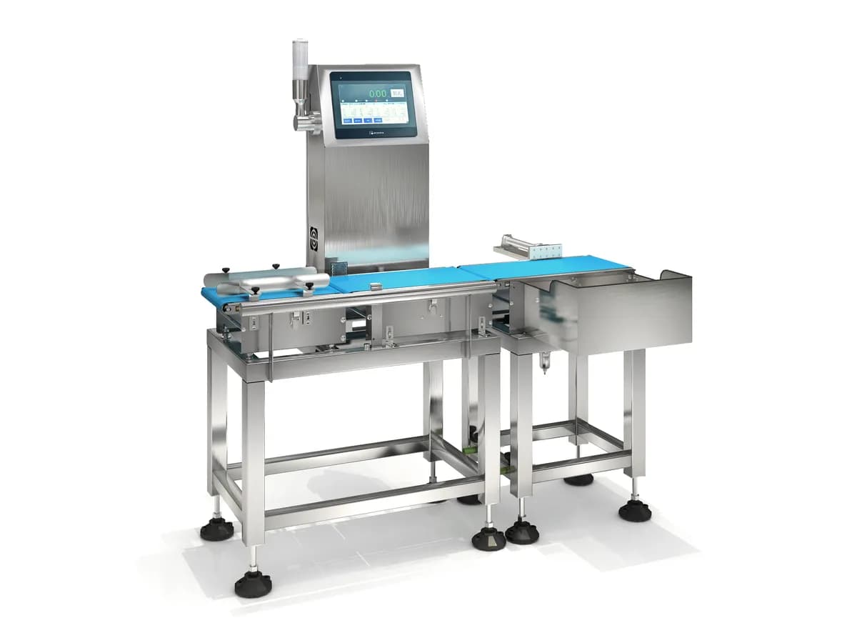
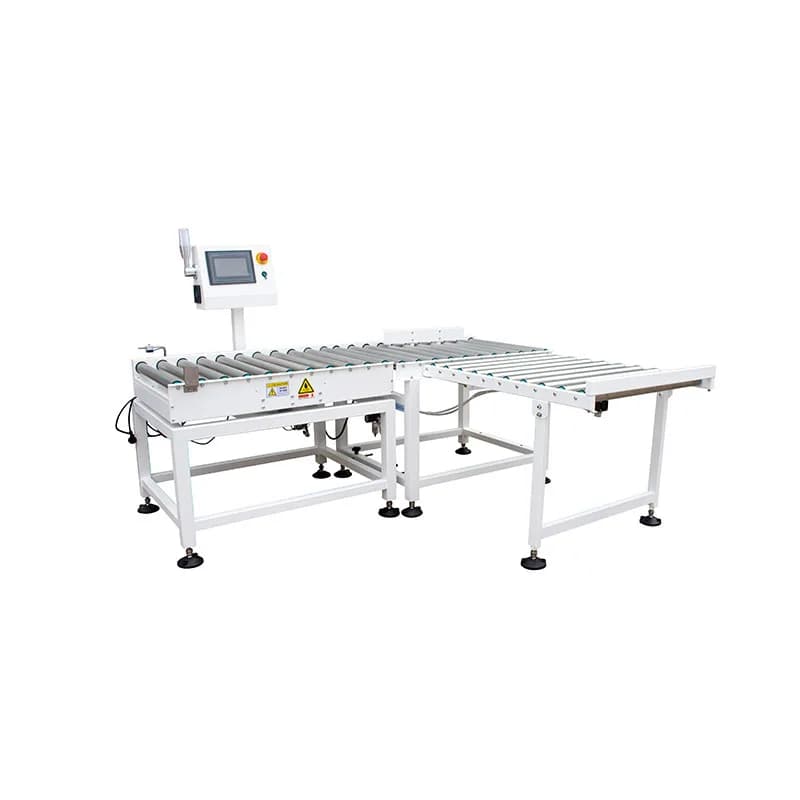
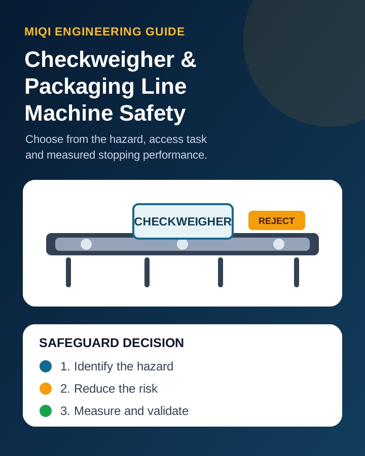
A checkweigher is rarely an isolated box. A working line can include two or three conveyor sections, transfer rollers, a weigh belt, a pusher, swing arm, flap, drop section or powered roller reject, a reject bin and an interface to filling, sealing, labelling, cartoning or palletising equipment. The assessment therefore has to cover the complete line interface and the work people actually perform.
Assess the transfer points and moving parts of both dynamic checkweigher models and weighing and counting packaging machines as one line. Checkweigher Reject Systems: Air Blast, Pusher, Flap, Arm, Wheel or Stop Alarm explains the pusher, flap and diverter arrangements whose motion and recovery access must be included in the guarding assessment.
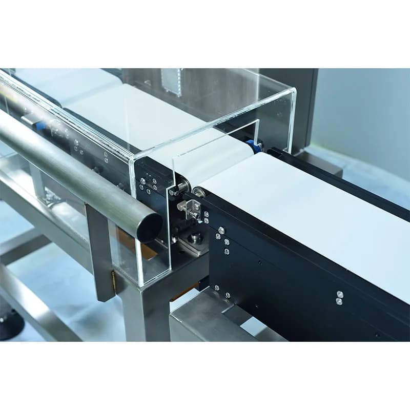
Separate normal production from product sampling, reject recovery, clearing a jam, cleaning, changeover, fault finding and maintenance. A position that is not approached during automatic running may become the most frequent hand-access point when a reject bin fills or a carton stops in front of a pusher.
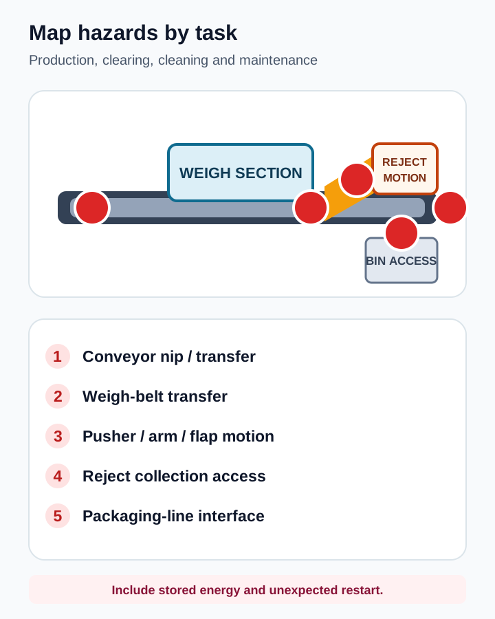
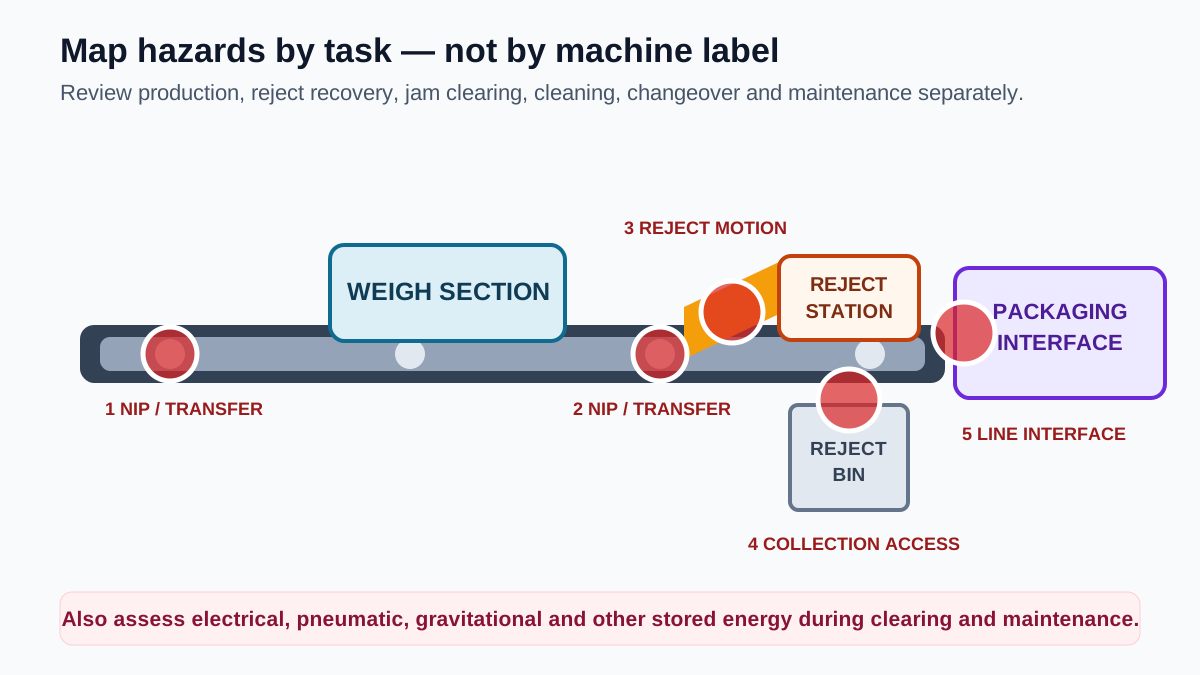
| Area or motion | How a person may approach | Question the risk assessment must answer |
|---|---|---|
| Infeed, outfeed and conveyor rollers | Guiding a product or reaching near a belt-to-roller transfer | Can the nip point be eliminated, reduced by design or physically guarded without creating a new trap? |
| Pusher, swing arm or flap reject | Clearing a jam, recovering a reject or reaching into a full collection area | What are the force, speed, stroke, stopping time and stored pneumatic or gravitational energy? |
| Reject bin or drop opening | Removing product while the machine or reject mechanism can still cycle | Can collection occur outside the hazard zone, and should bin removal or gate opening initiate a stop? |
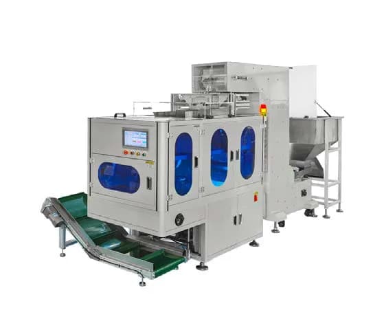
| Packaging-machine interface | Following material through an open infeed or outfeed aperture | Can a person reach or enter with the product, and is physical containment needed? |
| Cleaning and maintenance access | Entering after a stop command while energy remains available | How are electrical, pneumatic, hydraulic, gravity and other stored energy isolated and verified? |
2. Use the risk-reduction hierarchy before choosing a safeguard
ISO 12100 treats hazard identification, risk estimation, risk evaluation and risk reduction as the starting point. First ask whether the design can remove or reduce the hazard: lower a reject mechanism's force or speed, remove an accessible nip, reduce an opening, move a service point outside the danger zone or change the layout. Use guards or protective devices for the remaining risk. Warning labels, training and personal protective equipment do not replace a feasible engineering control.
- 1Define the machine boundary
Include upstream and downstream machines, all operating modes, personnel, material flow, utilities and reasonably foreseeable misuse.
- 2Identify hazards by task
Review production, loading, reject recovery, jam clearing, cleaning, changeover, setup and maintenance separately.
- 3Reduce risk at the source
Change force, speed, geometry, openings or layout before choosing a fixed guard, interlocked gate or electro-sensitive device.
- 4Design the whole safety function
Specify sensing or interlocking, safety logic, final switching or drive function, reset, diagnostics and fault response.
- 5Measure and validate
Test stopping, faults, reach-around, restart and isolation under real speed, load and adverse conditions, then retain the evidence.
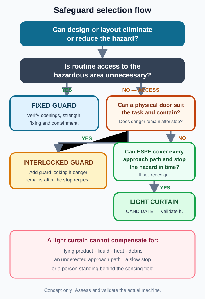
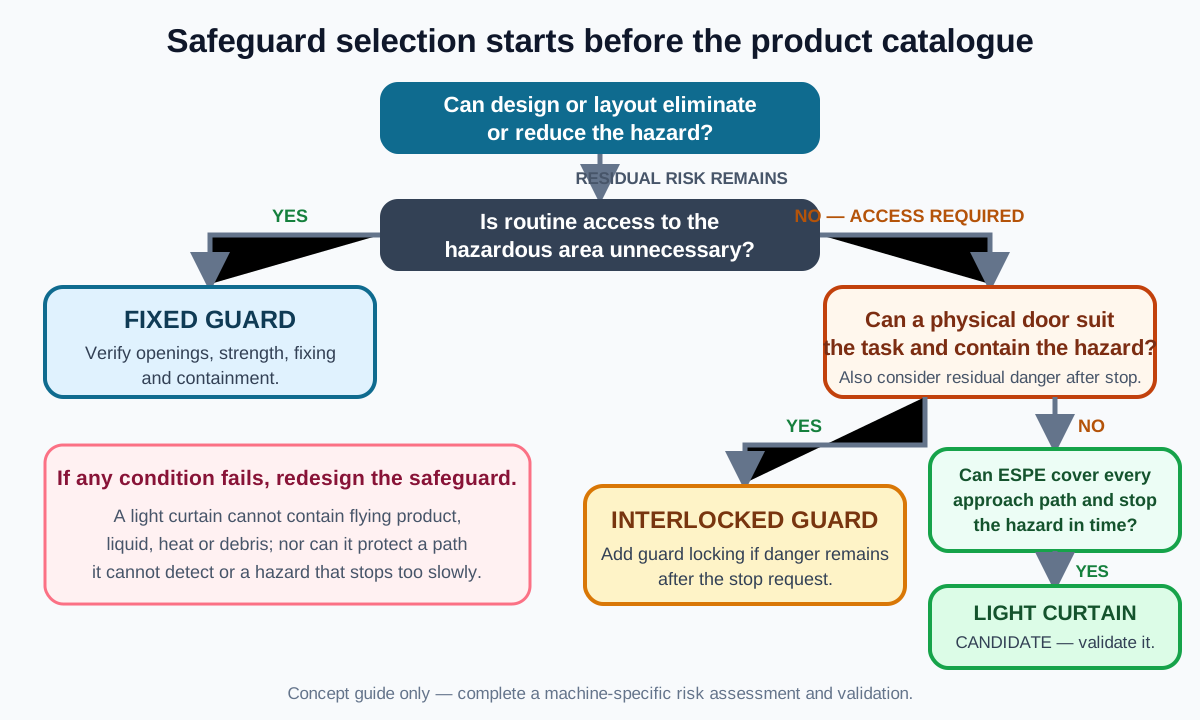
3. Fixed guard, interlocked gate, guard locking or safety light curtain?
| Method | Best fit | Critical limitation |
|---|---|---|
| Fixed guard or enclosure | Areas that need no routine access, conveyor nip points and locations that must contain ejected material | Removal for frequent work encourages non-replacement; openings, strength and fixing method still require verification. |
| Interlocked movable guard | Cleaning, changeover or adjustment access where opening the guard should issue a stop command | If a person can reach the hazard before it stops, simple interlocking is not enough. |
| Guard locking | Access doors where inertia, pressure, heat or another residual hazard remains after the stop command | Unlock conditions and escape or emergency release must be designed for the real machine. |
| Safety light curtain | An opening must remain accessible and the hazardous motion can be stopped before the person reaches it | It cannot contain flying objects, hot material, liquid or mechanical debris and it depends heavily on stopping performance. |
| Safety laser scanner or presence sensing | Larger floor areas, approach paths or detection behind a primary safeguard | The response time, field geometry, environment and possibility of standing behind the detection zone require validation. |
These methods are not mutually exclusive. A line may use fixed guarding around drives, an interlocked or guard-locked service door, a safety light curtain at a necessary open transfer and presence sensing where whole-body access is possible.
4. When is a safety light curtain suitable on a packaging line?
A safety light curtain can be appropriate at an open feed or discharge point, a reject station that must remain accessible, or an automated cell where a physical door would interrupt frequent access. The essential condition is that the hazardous motion can reach the safe state defined by the risk assessment before a person can reach the hazard.
- Consider it where the opening must remain available and the complete machine can stop reliably within the validated separation distance.
- Do not rely on it alone where the primary risk is a flying object, blade, hot surface, spray, pressure release or motion that continues too long after detection.
- Add further measures if a person can pass completely through the light curtain, stand behind it or bypass it from above, below or either side.
- If product must pass through the protective field, use a separately designed and validated muting function where permitted. If an approved blanking function is used, follow the device manufacturer's constraints and apply the required compensating measures. Never bypass or permanently suppress beams as an ad hoc workaround.
5. Specify the safety light curtain from the application, not the brochure headline
| Parameter | What it means | Packaging-line consequence |
|---|---|---|
| Detection capability or resolution | The smallest test object reliably detected in the protective field | It affects reach-through allowance and suitability for finger, hand or body detection. |
| Protective height | The effective continuously monitored height | It must cover the approach path; housing length is not automatically protective height. |
| Operating range | The permitted transmitter-to-receiver distance | Allow for aperture width, alignment, vibration, reflective surfaces, dust, mist and mounting margin. |
| Response time | Time from interruption to the output reaching its specified state | It is only one part of total response; logic, final elements and machine stopping time must be added. |
| Output architecture | For example dual-channel Output Signal Switching Device (OSSD), relay or another defined interface | It determines how the device is connected to a safety relay or safety PLC and how faults are detected. |
| Environment and evidence | Ingress protection, temperature, washdown, vibration and the exact certificate scope | Confirm the ordered model and target market; do not generalise one document to an entire family. |
For project discussions, DAIDISIKE DQA and DQC families can be treated as light-curtain candidates, while DQSA is an area or perimeter detection concept rather than a physical guard. Before either light-curtain family is proposed, verify the exact ordered model's documented device type, output architecture, response time, claimed PL or SIL suitability and certificate scope; a family name is not evidence of those properties. A non-contact door monitor such as DX-C1 reports guard position but does not hold a door closed. A guard-locking device such as DX-W2 is the relevant type to evaluate when residual danger remains after a stop request. None of these component names, by itself, proves the performance level of the complete machine.
6. A light curtain only works as part of a complete safety function
When the protective field is interrupted, the device outputs change state. A safety relay or safety PLC evaluates the channels and faults. Final switching elements or a validated drive safety function then bring the hazardous motion to the safe state. The sensor, logic and final element must be designed and validated as one chain.
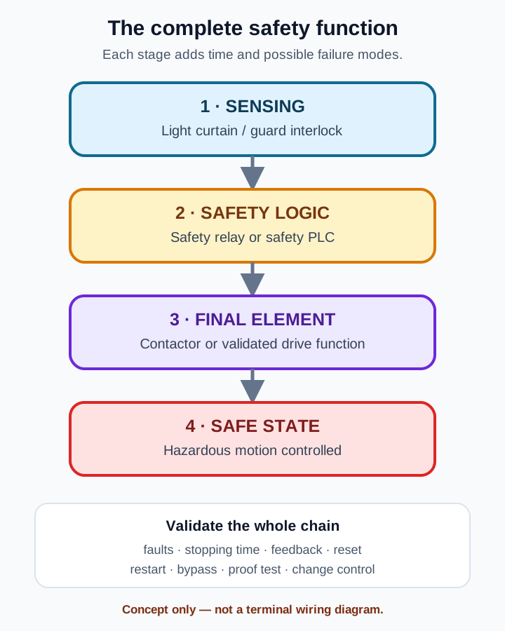
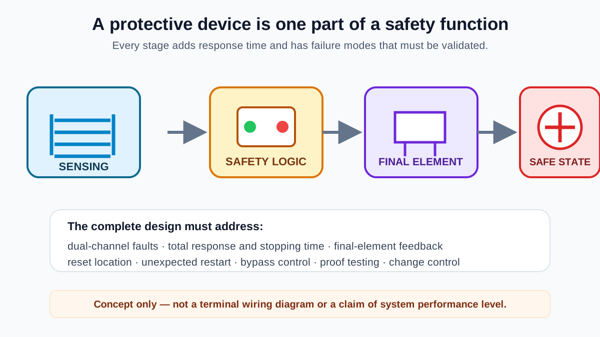
A standard PLC may receive status and diagnostic signals, but reading a light-curtain signal does not by itself establish a safety function. The safety-related stop must be implemented by an architecture suitable for the required risk reduction and verified for broken wires, short circuits, contactor or drive faults, response time and restart behaviour.
7. Separation distance, reset and restart are different engineering questions
Do not copy a universal light-curtain distance from a web page
The separation distance depends on the applicable approach parameters, detection capability, light-curtain response, safety-logic response, final-element response, measured machine stopping time and application uncertainty. ISO 13855:2024 addresses positioning methodology. Without a stopping-time measurement on the actual machine and operating condition, no fixed distance can be declared safe for every checkweigher or packaging line.
A clear protective field is not the same as permission to restart
Clearing the field only means the detection zone is no longer interrupted. The risk assessment and control design must decide whether a manual reset is needed, where the reset control is located, whether a separate start command is required and whether automatic restart is permissible. Reset should not itself initiate hazardous motion.
Whole-body access creates a stand-behind problem
If a person can pass through the light curtain and remain inside the safeguarded space, an outside operator may see a clear field while someone is still at risk. Evaluate additional presence detection, controlled reset, escape release, visibility and energy isolation instead of treating a clear light curtain as proof that the area is empty.
8. Jam clearing and cleaning require hazardous-energy control
A stopped pusher can still contain pneumatic pressure. A flap, lift or diverted product can move under gravity. Conveyors can restart through automatic sequencing, remote commands or upstream and downstream line logic. When jam clearing, entry, guard removal, cleaning or maintenance exposes personnel to unexpected energisation or stored energy, apply the site-specific hazardous-energy-control procedure, including isolation and verification, under the rules applicable at the installation site.
- Define who is authorised to stop, isolate, lock, verify and restore the machine; do not rely on a verbal warning.
- For pneumatic reject mechanisms, address the isolation valve, residual pressure and any part that can fall or spring back.
- Confirm that upstream or downstream equipment cannot restart the section through line interlocking while a jam is being cleared.
- Do not return a bypassed or removed safeguard to automatic production until it has been restored and functionally checked.
- Put clearing and cleaning steps into the handover documents and training record, not only on a caution sticker.
9. Installation and acceptance checklist
| Check | On-site verification |
|---|---|
| Hazard-zone coverage | Inspect conveyor nips, reject stroke, collection area, drop opening, doors and every upstream or downstream interface. |
| Reach-around and stand-behind | Try realistic paths above, below and beside the device; assess whether a person can enter and remain inside. |
| Stopping performance and distance | Measure the complete response and machine stopping time at real speed, load and adverse conditions; then validate positioning. |
| Safety control chain | Test interruption, wiring faults, diagnostics and final-element feedback; confirm normal control cannot bypass the safety stop. |
| Reset and restart | Confirm field clearance does not cause an unintended restart and that the reset location gives a suitable view of the hazard zone. |
| Guard door and locking | Open each door and verify the stop command; where stopping is delayed, verify that access remains prevented until danger has ended. |
| Jam clearing and isolation | Perform the actual stop, isolation, pressure release, lock, verification and restoration sequence, including line interfaces. |
| Documentation and change control | Retain the risk assessment, circuit, ordered-model documents, certificate scope, stopping test and validation record; reassess after speed or mechanism changes. |
This checklist helps a project team find omissions. It does not replace a model-specific risk assessment, safety-control design or validation by competent personnel under the laws and standards applicable at the installation site.
Continue your equipment evaluation
Technical references
- ISO 12100:2010 — Safety of machinery — Risk assessment and risk reduction
- ISO 14120:2015 — General requirements for guards
- ISO 14119:2024 — Interlocking devices associated with guards
- ISO 13855:2024 — Positioning of safeguards
- ISO 14118:2017 — Prevention of unexpected start-up
- IEC 61496-1:2020 — Electro-sensitive protective equipment
- IEC 61496-2:2020 — Active opto-electronic protective devices
- IEC 62046:2026 — Application of protective equipment to detect the presence of persons
- ISO 13849-1:2023 — Safety-related parts of control systems — Design
- ISO 13849-2:2012 — Safety-related parts of control systems — Validation
- ISO 13857:2019 — Safety distances for upper and lower limbs
- UK HSE — Packaging machinery hazards and guarding
- OSHA 1910.212 — General requirements for all machines
- OSHA 1910.147 — The control of hazardous energy